Contact: sales@haomai.net
NEWS
Company News
500kV Transformer High-Voltage Load Simulation Test | HTB-8000 Circuit Validation & Phase Compensation Workflow
1. Equipment Overview
Deployed HTB-8000 High-Current/Voltage System (3x HTB-8000B parallel current sources, 3x HTB-8000C series voltage sources) with integrated capacitive compensation to overcome large transformer impedance.
2. Capacitive Compensation Principle
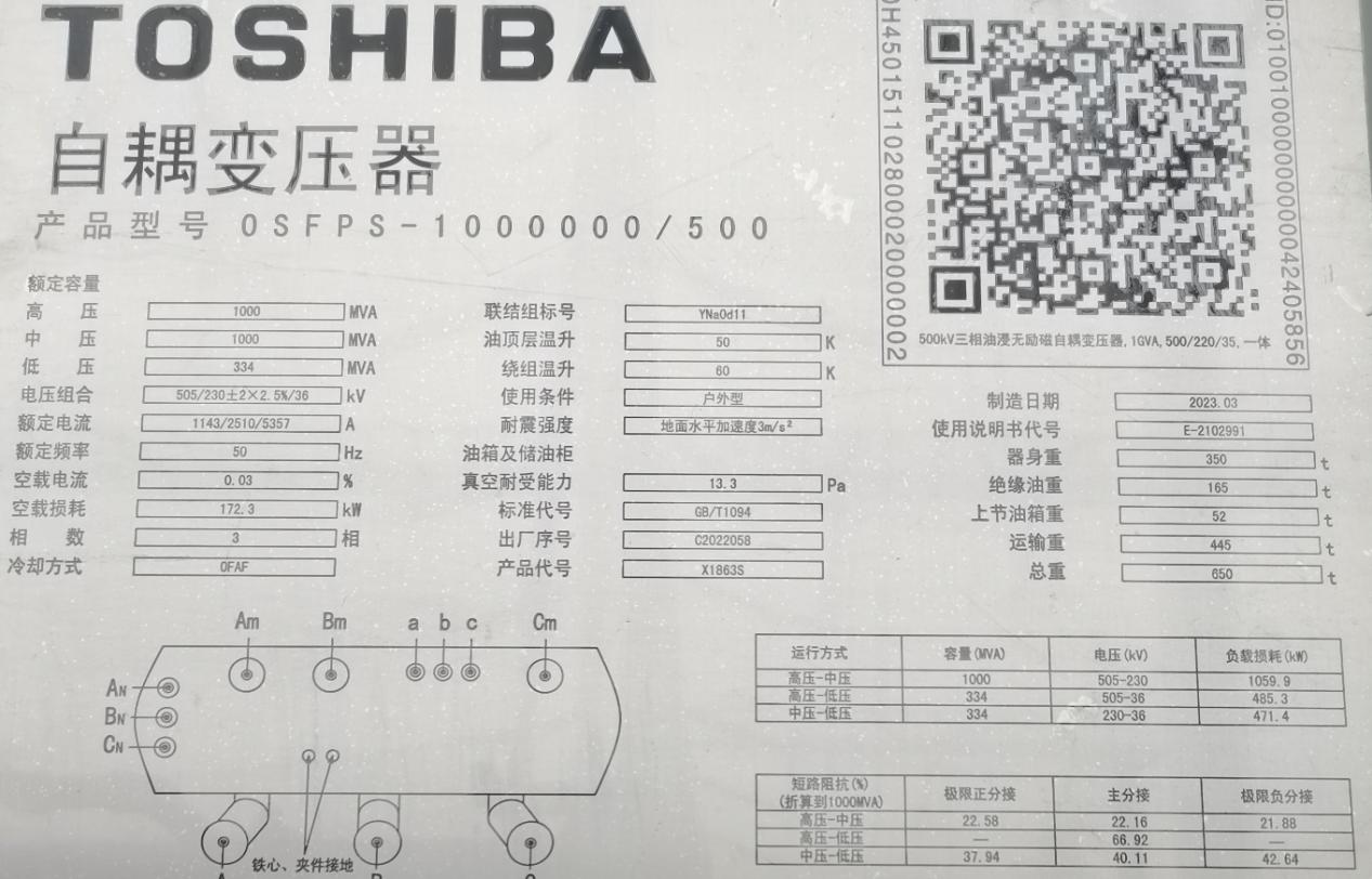
To address transformer short-circuit impedance (22.16% per nameplate), the test circuit uses:
? Series Capacitors: Partial inductive compensation for reduced system impedance.
? Parallel Capacitors: Achieve near-resonance (cosφ → 0) to minimize active power consumption.
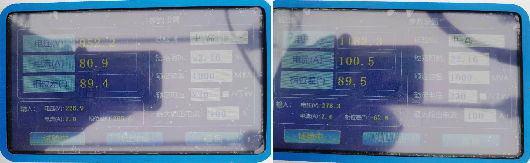
This dual compensation allows 100A testing at 1300V with only 2kW input power.
3. Wiring Configuration
Phase-A Power Injection
△ Phase-A capacitive wiring
-
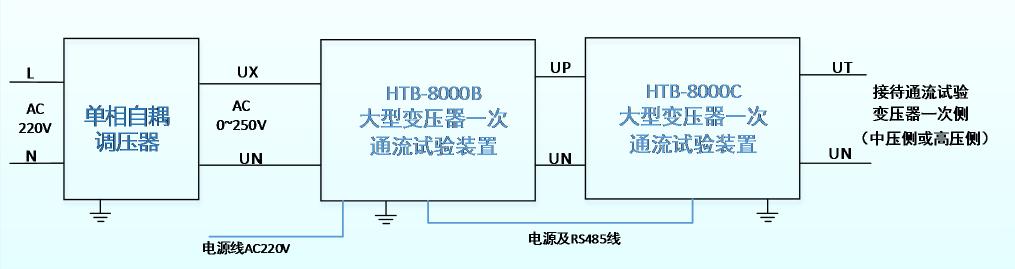
AC380V Single-Phase Variac → HTB-8000B (controls parallel caps) → HTB-8000C (series caps).
-
Maintained 120° phase separation using shared neutral line.
2)Transformer Interface:
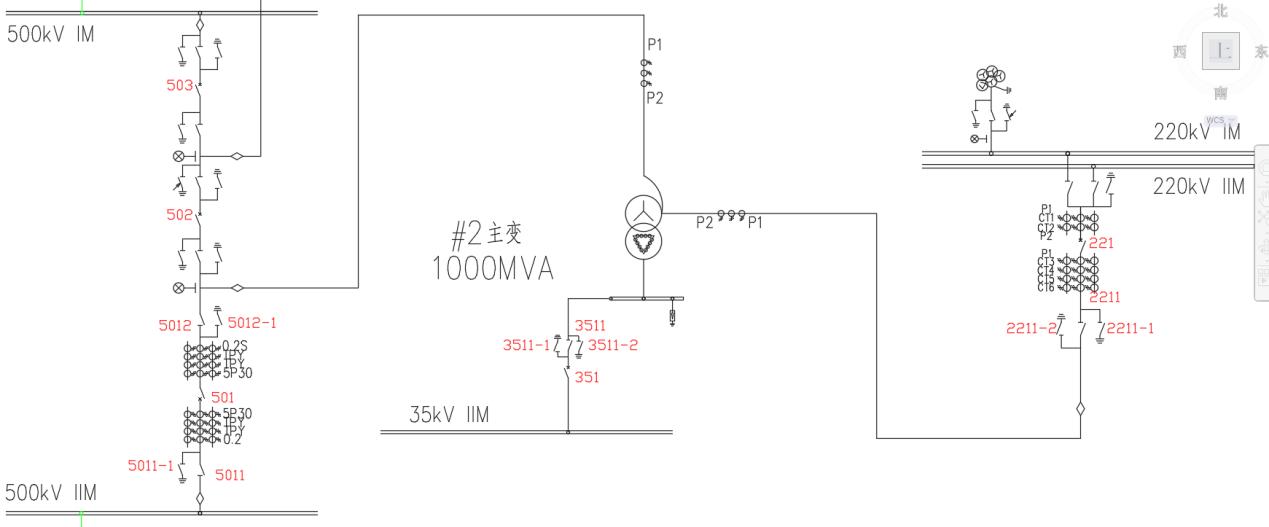
- Grounding disconnects: 2211-1/2211-2 open.
- Current injection via CT P1 terminal (中壓側(cè)), short circuit at 5011-1 (高壓側(cè)).
4. Field Safety Protocols
- ? CT Secondary Circuits: Never opened under current flow.
- ? Grounding Integrity: All HTB-8000 units bonded to substation grid.
- ? Guarded Zones: Isolate test areas from live equipment.
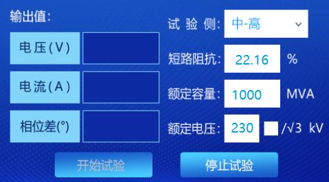
- Plugged 1000MVA capacity and 22.16% impedance into HTB-8000B controller.
- Calculated test voltage: 1172V @100A (Z=11.72Ω).
6. Results & Validation
- Theoretical Differential: 0A (matched protection system readings).
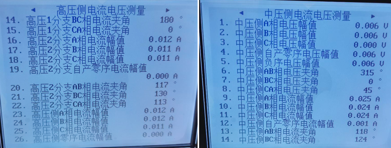
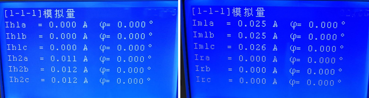
- YD-300 Wireless Analyzer: Confirmed 0.011A (HV) vs 0.025A (MV) secondary currents.
- Near-Zero Differential Drift: Both Protection A/B suites showed <0.005A imbalance.
△Transformer protection relay A sampling
△ Transformer protection relay B sampling
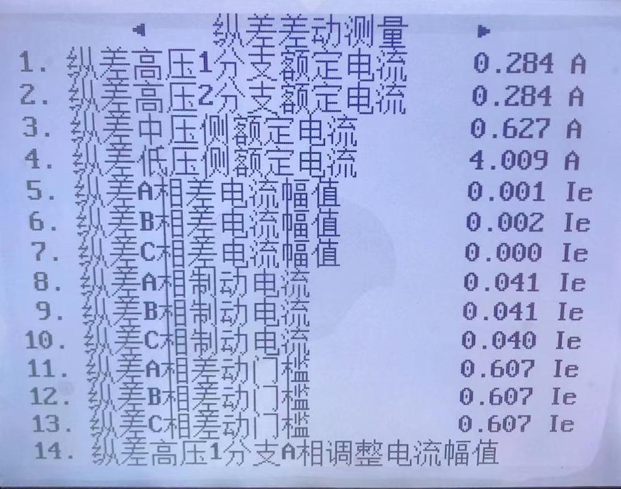
△ Transformer protection relay differential value reading
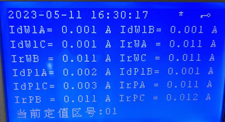
△Transformer protection relay differential value reading
24-hours hot line 400-099-8859 technical hot line: 13971234137

Copyright ? 2024 All rights Reserved.
備案號:鄂ICP備05010718號-1